Long, long time ago…
Back in the late 2000s, I spent a significant amount of my time at Intel working on Moblin, an open-source Linux platform for mobile devices. That work eventually led to a collaboration between Intel and Nokia to merge Moblin and Maemo into what became MeeGo.
It was an exciting time. I spent many memorable days in Helsinki working alongside Nokia engineers, and the collaboration was one of the main reasons I eventually moved from Montreal to London. Unfortunately, MeeGo’s story was cut short when Nokia changed direction in 2011. It was fun while it lasted, though, and certainly an experience I still look back on fondly.
One of the few tangible things I still have from those days is a Nokia N900. Surprisingly, more than 15 years later, the device has aged remarkably well. It still works, and even the original battery holds a charge! For years, it sat in a box alongside various other mementos from that era, largely forgotten.
That changed over a recent long weekend when I went looking for a fun technical project. I wanted something that would be both an interesting challenge and an opportunity to explore some of the gaps in Zephyr, particularly around hardware enablement and out-of-tree platform support. The N900 seemed like the perfect candidate.
Porting an RTOS to an entirely new platform is normally a significant undertaking. Depending on the hardware, documentation, and existing software support, it can easily take days, weeks, or even months. But this time, I had an additional tool at my disposal: an AI coding agent.
Using Claude, I managed to get Zephyr running on the N900 in just one day.
Of course, this wasn’t AI magically creating an entire hardware port from scratch. Much of the necessary infrastructure and functionality already existed in Zephyr, and the AI agent was able to build on that foundation, connect the pieces, and help fill in the gaps. The N900’s age actually worked in our favor: more than 15 years of existing Linux support provided valuable references for understanding and initializing the hardware. It is also a remarkably developer-friendly device, with no need for jailbreaking, bypassing locked bootloaders, or dealing with many of the restrictions common on modern smartphones.
What started as a small weekend experiment turned into an interesting demonstration of just how much existing Zephyr infrastructure can be reused, how practical out-of-tree platform support can be, and how AI-assisted development can dramatically accelerate the process.
Here’s how it went.
Can Zephyr run on a Nokia phone?
The Nokia N900 has a TI OMAP3430: one ARM Cortex-A8 core at 600 MHz, 256 MB of SDRAM and an 800×480 LCD. Zephyr had no Cortex-A8 support and nothing for the OMAP3 family. It did have ARMv7-A support for the Cortex-A5, A7 and A9, a Cortex-A/R interrupt path that can take a custom interrupt controller, and a 16550 UART driver that matches the OMAP3 UARTs.
The constraints were set by the phone itself. Its bootloader, NOLO, is signed, and the OMAP3430 in a retail N900 is a high-security part that runs our code in the non-secure world. The serial port is on 1.8 V test pads under the battery. Mainline QEMU has no model of this phone. Whatever we built had to be loaded by NOLO and debugged through the screen.
Talking to NOLO
The open source Maemo flasher 0xFFFF is packaged in Ubuntu and ships its own udev rule. With the phone powered off and USB plugged in, it caught the OMAP boot ROM first, then NOLO:
Found USB device: (not detected)
Detected OMAP3430 chip (revision 87)
Sending OMAP memory boot message...
Found USB device: SU-18/RX-34/RX-44/RX-48/RX-51/RM-680/RM-696 (0x421:0x105) in NOLO mode
Device: RX-51
HW revision: 2101
NOLO version: 1.4.14
Software release version: RX-51_2009SE_10.2010.19-1_PR_MR0
R&D mode: disabled
Two features made the whole project safe. 0xFFFF -m kernel:image.bin -l -b loads an image into RAM and boots it without writing flash, so pulling the battery always returns the phone to Maemo. And because the boot ROM itself answers on USB, the phone can be cold-flashed even if something on it breaks. We also turned on R&D mode with the watchdog flags, which turned out to matter less than expected (see Watchdogs).
A 472-byte smoke test
Before writing any Zephyr code we checked the one thing everything else depended on: does NOLO run our code? The test image disables the MPU watchdog, reads the framebuffer address and format from the display controller NOLO already set up, and fills the screen red, green, blue and white in a loop. It carries a zImage header in case NOLO checks for one.
The first build failed review before it reached the phone: a constant color table was referenced through an absolute address, which would break if NOLO loaded the image anywhere other than its link address. Computing the colors in code made the image fully position-independent. The phone cycled through the four colors on the first try.
Finding: Without a serial port, the display controller NOLO leaves running is the most useful debug output there is. Every later diagnostic in this log builds on it.
The port
The first version of the port added these pieces, each of which became its own commit:
- Cortex-A8 CPU support: a Kconfig symbol, the GCC
-mcpumapping, the IAR name, the mcumgr processor name and a devicetree binding. - An interrupt controller driver for the OMAP3 INTC. The Cortex-A/R entry code re-enables interrupts while a handler runs, so acknowledging an interrupt masks its line and lets the controller sort the next one; end of interrupt unmasks it again.
- A system timer on GPTIMER1. This went through five versions (see the timer saga).
- The OMAP3 SoC: devicetree, MMU regions, clocks, a reset hook that leaves the caches and MMU in a known state, and VBAR pointing at the vector table in the image, because address 0 is boot ROM.
- A position-independent entry stub. NOLO jumps to the first byte of the image wherever it loaded it. The stub copies the image to its link address and enters the kernel there. The source and destination can overlap the stub itself, so the copy routine first moves itself above both ranges and runs from there, the way the Linux zImage decompressor does.
- A console on the LCD, drawing
printk()output with the character framebuffer fonts already in the tree: 80 columns by 30 rows.
Four boots to a running kernel
- Boot 1: NOLO loaded the 811 KB image and the phone dropped off USB, but the screen kept showing NOLO’s logo. Our code ran and died before the console started, with no way to tell where.
- Boot 2: Each early stage now painted its own colored band into NOLO’s framebuffer, and after the MMU came on a stage set the whole screen to a solid color. The screen ended dark blue with no text: every stage had passed, the console had started, and the kernel died right after. The vector table sits in the first page of the image, ahead of the code region the ARMv7 MMU code maps, so the first timer interrupt vectored into an unmapped page and looped in prefetch aborts without printing anything. The SoC now maps that page.
- Boot 3: The console printed a fault: a synchronous external abort on an
ldrexin the kernel’s time-slicing code, on ordinary RAM. Zephyr marks all Normal memory Shareable. On this uniprocessor Cortex-A8 the exclusive access then went out to the OMAP3 memory controller, which rejects it. A new MMU option leaves Normal memory non-shareable on the Cortex-A8 and changes nothing elsewhere. - Boot 4: The ticker thread kept updating. Threads, semaphores, timed sleeps, the timer interrupt and the interrupt controller all worked. The stock
synchronizationsample ran next and scrolled cleanly.
- band 1 · red · entry stub running, caches cleaned
- band 2 · orange · image moved to its link address
- band 3 · yellow · soc_reset_hook entered
- band 4 · green · caches, MMU state and watchdog handled
- band 5 · cyan · z_prep_c started
- band 6 · white · interrupt controller up
- whole screen · magenta · MMU on, kernel init started
The boot-stage bands stayed in the tree as CONFIG_SOC_OMAP3_BOOT_STAGES. They only need the framebuffer NOLO left behind, so they work before the MMU, the console or any driver exists.
Finding: Two of the three boot failures were generic ARMv7 assumptions that no other Zephyr board had tripped: vectors mapped only when copied to address 0, and shareable memory everywhere. A new core finds the corners of an architecture port.
A display driver and LVGL
NOLO configures the panel and the display controller, so a Zephyr display driver only has to take over the graphics layer. The driver points it at a 2 MB framebuffer reserved at the top of SDRAM, in XRGB8888, and serves the display API through the framebuffer helpers already in the tree. The console moved into the same reserved buffer, which took its 750 KB buffer out of the image: hello_world went from 811 KB to 41 KB, which also made every USB load faster.
The stock LVGL sample built after a board default for the XRGB8888 color format. It showed “Hello world!” and a counter on the phone.
The same day also added a nolo west runner, so west flash waits for the phone in NOLO’s USB mode and RAM-boots the image.
Three watchdogs and a battery
With longer runs, the phone started restarting itself. A diagnostic app printed the counters of the two OMAP watchdogs once a second:
WDT2 WCLR 0x00000020 WLDR 0xfffb0000
WDT3 WCLR 0x00000020 WLDR 0xfffb0000
t= 0s WDT2 fffb04b3 WDT3 fffbcfeb
t= 1s WDT2 fffb04b3 WDT3 fffc5005
t= 2s WDT2 fffb04b3 WDT3 fffcd025
t= 5s WDT2 fffb04b3 WDT3 fffe5085  -> stopping WDT3
t= 6s WDT2 fffb04b3 WDT3 fffe5098
t= 7s WDT2 fffb04b3 WDT3 fffe5098
WDT2, the MPU watchdog, was already stopped by our reset hook. WDT3, the IVA2 watchdog, was counting at 32 kHz toward a 10-second timeout that NOLO had started, R&D mode or not. The reset hook now stops both.
Then the phone began switching itself off, which is different from a reset: it stayed dark and NOLO never came back. Two runs died at exactly 150 seconds, which looked like the watchdog in the TWL5030 power chip, so the board learned to stop that one too. The next run died at 110 seconds. A shrinking lifetime is a battery, and the fuel gauge later confirmed it: 8%. Nothing charges the phone while NOLO or Zephyr runs. After a charge the same image ran past 960 seconds.
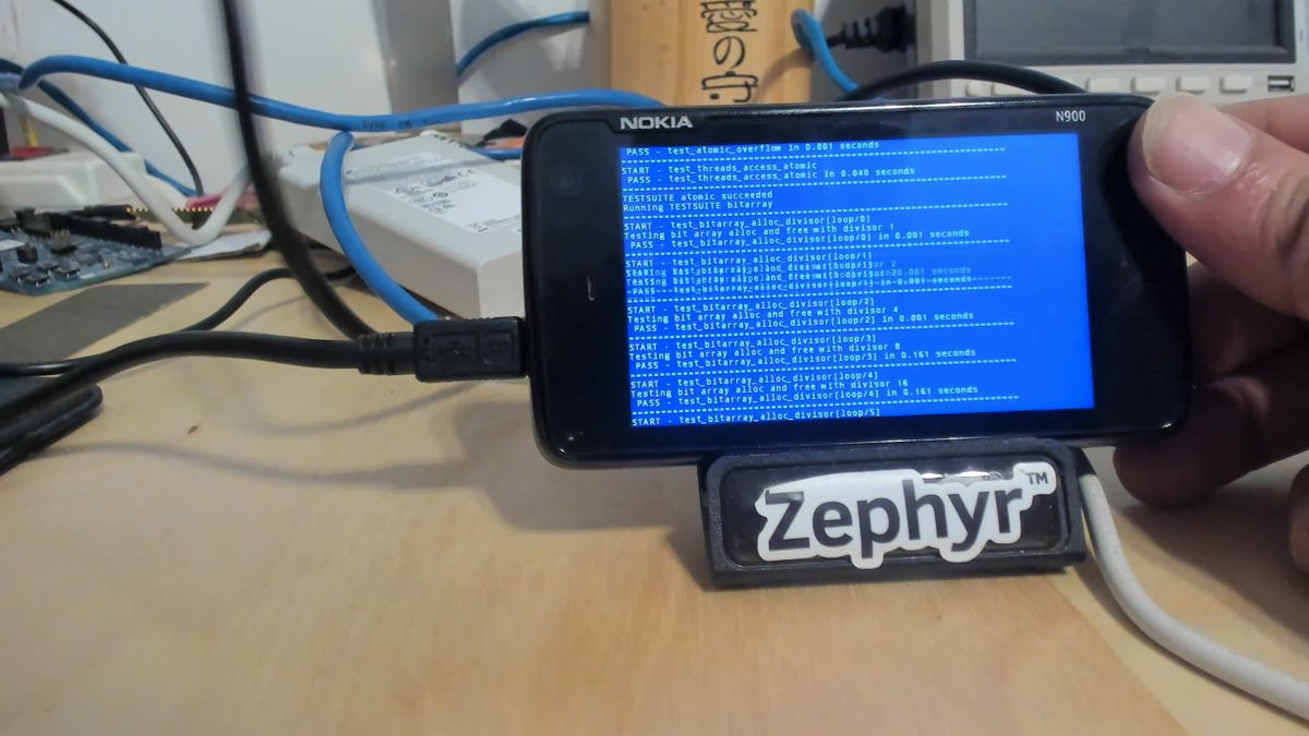 13:23:46 · kernel/common in the bitarray tests
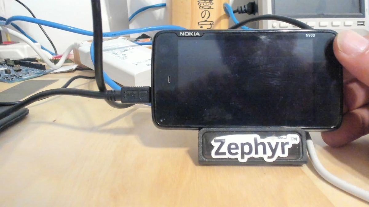 13:23:47 · one second later: screen and LED off. The battery, not the test.
A camera on the bench
Reading results off the phone and typing them into chat stopped scaling, so a Logitech Brio went on the bench, plugged into the build machine. Autofocus locked onto the background. A sweep of the manual focus setting, scored by edge contrast in the screen area, found the sharp point (85 at first, 70 after the camera moved):
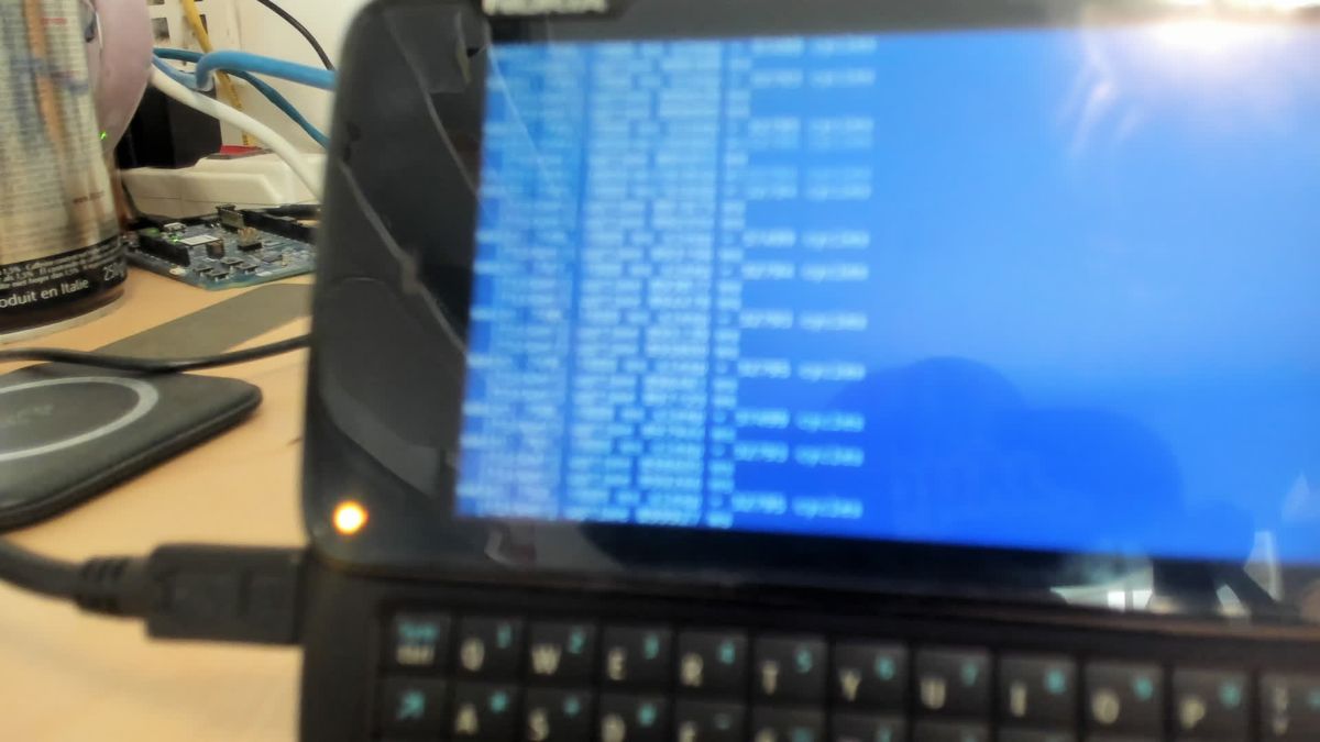 First frame, autofocus: unreadable
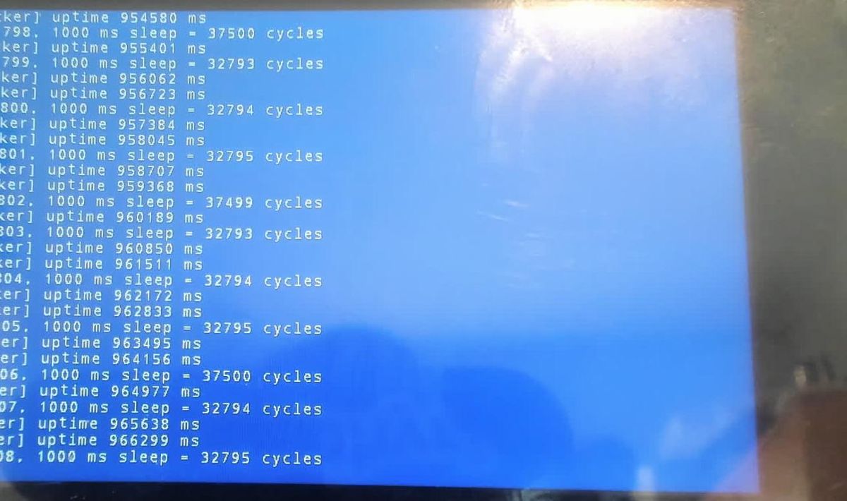 Manual focus: uptime 966 s on a charged battery
That second frame showed something new. The ticker sleeps 500 ms but its lines came every 661 ms, and some 1-second sleeps measured 1.144 s. Every new console line copies the whole 750 KB framebuffer in uncached memory with interrupts locked, about 150 ms. Timekeeping was fine; the console is slow to scroll. It was fixed later by moving the base address instead.
The camera now records one frame per second all the time, with the time in the file name. A test runs in a few seconds and its assertion message scrolls away in less, so reading the recording afterwards beats any single snapshot.
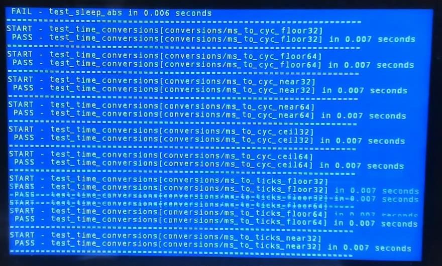 A failure caught by the recording: FAIL - test_sleep_abs, the frame before it scrolled away
The timer saga
The system timer needed five versions. Each one passed more tests and exposed the next problem:
| # | Design | What broke | Fix |
|---|---|---|---|
| 1 | 32 kHz, auto-reload every tick; cycle count derived from announced ticks | k_busy_wait() with interrupts locked hung: the cycle count stopped advancing |
Free-running counter as cycle count, compare match per tick |
| 2 | 32 kHz, 1024 ticks/s, free-running counter | test_k_sleep and test_timer_remaining: 1024 ticks/s doesn’t divide a millisecond, so sleeps rounded 1 ms over |
Tickless at 32768 ticks/s on the generic timer core |
| 3 | 32 kHz tickless, non-posted registers | test_sleep_abs, test_timer_remaining: every register access stalls 60–90 µs while it syncs with the 32 kHz clock |
Posted mode: writes complete in the background |
| 4 | 32 kHz tickless, posted | test_usleep too slow: each k_usleep(1) took 823 µs |
Run the timer from the system clock |
| 5 | 19.2 MHz SYS_CLK, tickless, 10 000 ticks/s, posted | Nothing so far |
The 823 µs came from the timer core’s guard for equality-match hardware. A compare written after the counter has passed it never fires until the counter wraps, so the core writes the compare, reads the counter back and pushes the target out if it is less than the lead (8 cycles) ahead, doubling the push each time. A one-tick sleep always starts too close, and each rewrite also waited about 3 cycles for the previous posted write. The target settled 27 cycles out:
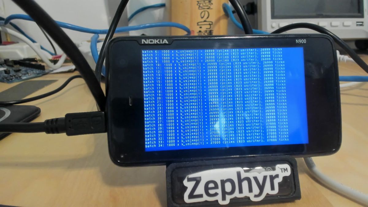 32 kHz: 1000 × k_usleep(1) = 26 999 cycles, 823 µs each
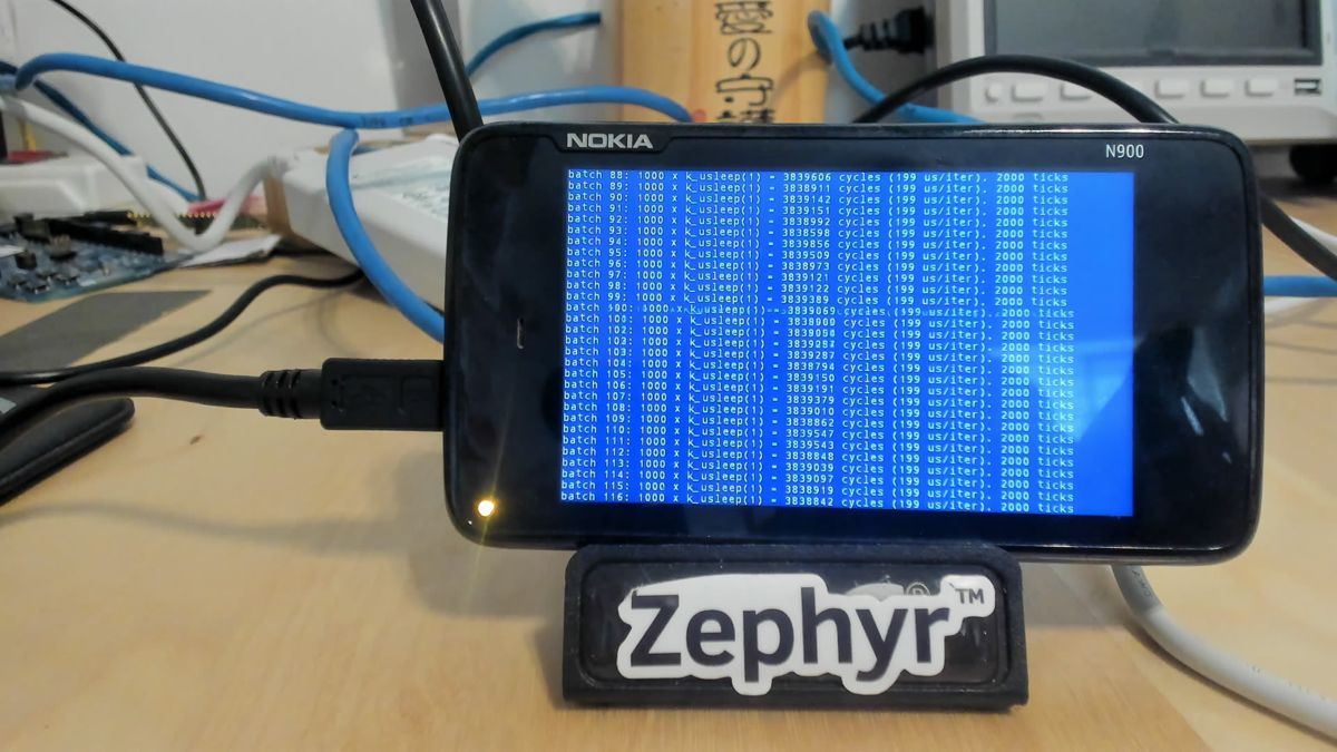 19.2 MHz: 199 µs each, exactly 2 ticks
Before switching clocks we measured instead of assuming. The PRCM registers said SYS_CLKIN_SEL = 2 (19.2 MHz) with divider 1, and counting a second timer on SYS_CLK against the 32 kHz timer gave 19 199 392 Hz:
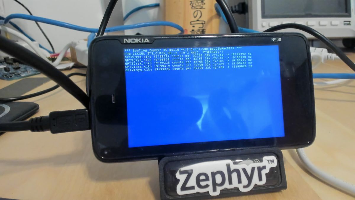 SYS_CLK measured against the 32 kHz clock: 19.199 MHz, within crystal tolerance
/* Posted mode: only a second write to the same register waits for the first */
static void gpt_write(uint32_t val, mm_reg_t reg, uint32_t pending)
{
	while ((sys_read32(GPT_TWPS) & pending) != 0U) {
	}
	sys_write32(val, reg);
}
Finding: A 32 kHz timer behind a clock-domain crossing is fine for timekeeping and poor for short sleeps. The same tests that passed on Nordic’s 32 kHz RTC needed a fast clock here because every register access pays for the crossing.
Test results
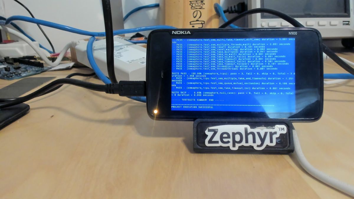
Every result below was read from the phone’s screen by the camera. All runs are RAM boots through NOLO.
| Suite | Timer version | Result | Notes |
|---|---|---|---|
| samples/synchronization | 1 | PASS | Threads alternate, console scrolls |
| LVGL sample | 2 | PASS | “Hello world!” and counter |
| kernel/common | 2 | PASS | irq_offload, nested offload, printk, bitarray |
| kernel/context | 2 | 1 FAIL | test_k_sleep: 1024 ticks/s rounding |
| kernel/context | 3 | PASS | test_timer_interrupts now runs too |
| kernel/timer/timer_api | 2 | 1 FAIL | 18 pass, 1 fail, 1 skip |
| kernel/timer/timer_api | 3 | 2 FAIL | test_sleep_abs, test_timer_remaining |
| kernel/timer/timer_api | 4, 5 | PASS | 20 / 20 |
| kernel/sleep | 4 | SLOW | test_usleep: 823 µs per sleep |
| kernel/sleep | 5 | PASS | test_usleep in 1.001 s; wraparound passes |
| kernel/mutex/mutex_api | 5 | PASS | Priority inheritance, timeout races |
| kernel/semaphore | 5 | PASS | semaphore_null_case reports no tests |
| kernel/common | 5 | PASS | All suites; rebooted itself into the next test |
| kernel/context | 5 | PASS | context_one_cpu 5 / 5, test_k_sleep 6.844 s |
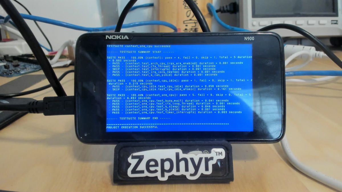 kernel/context passing on the tickless timer
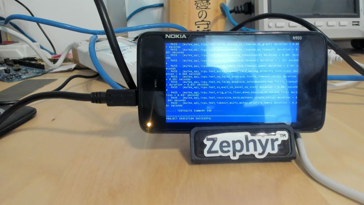 mutex_api on the 19.2 MHz timer
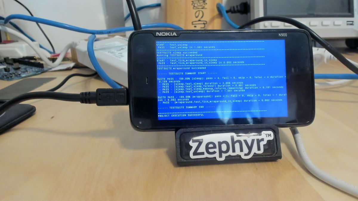 kernel/sleep: test_usleep in 1.001 s
 kernel/semaphore
Charging its own battery
The N900 charges through a TI bq24150A on I2C2, not through the TWL5030 power chip. That needed two new drivers: an I2C driver for the OMAP3’s older register layout, and a charger driver behind Zephyr’s charger API.
The bq24150A keeps the host’s settings only while the host resets its 32-second timer. When the timer runs out it falls back to a default mode that charges to 3.54 V. The driver resets it every 10 seconds and reapplies the settings after a fallback. If Zephyr hangs, charging drops to the safe default by itself. The settings come from the Linux N900 devicetree: 4.2 V, 650 mA, 100 mA termination, 68 mΩ sense resistor, plus a 500 mA USB input limit.
battery monitor: charger ready
t=  0s online charging health=1 ichg=650mA vreg=4200mV ilim=500mA regs=10 48 8c 4b 99
       gauge: 3754 mV, 8%, 33.7 C, flags 90
t=  5s online charging health=1 ichg=650mA vreg=4200mV ilim=500mA regs=10 48 8c 4b 99
       gauge: 3796 mV, 8%, 33.7 C, flags 90
...
t=160s online charging health=1 ichg=650mA vreg=4200mV ilim=500mA regs=10 48 8c 4b 99
gauge: 3796 mV, 9%, 34.5 C, flags 90| Register | Read | Meaning |
|---|---|---|
| status | 0x10 | Charging, no fault |
| control | 0x48 | 500 mA input limit, termination enabled, charging enabled (CE is active low) |
| voltage | 0x8c | VO = 35: 3.5 V + 35 × 20 mV = 4.20 V |
| vendor | 0x4b | Vendor 010: TI |
| current | 0x99 | 650 mA charge, 100 mA termination. Bits 7 and 3 read back as 1; bit 7 is written as 0, since 1 resets every register. |
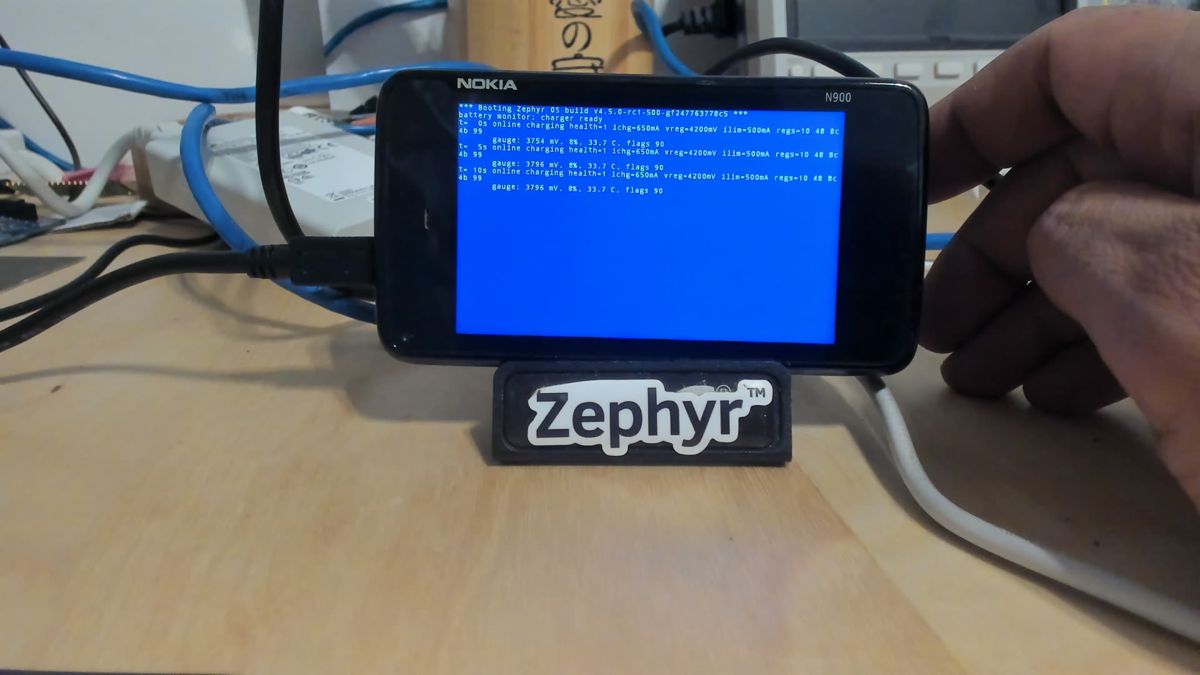 Charging starts at 8%
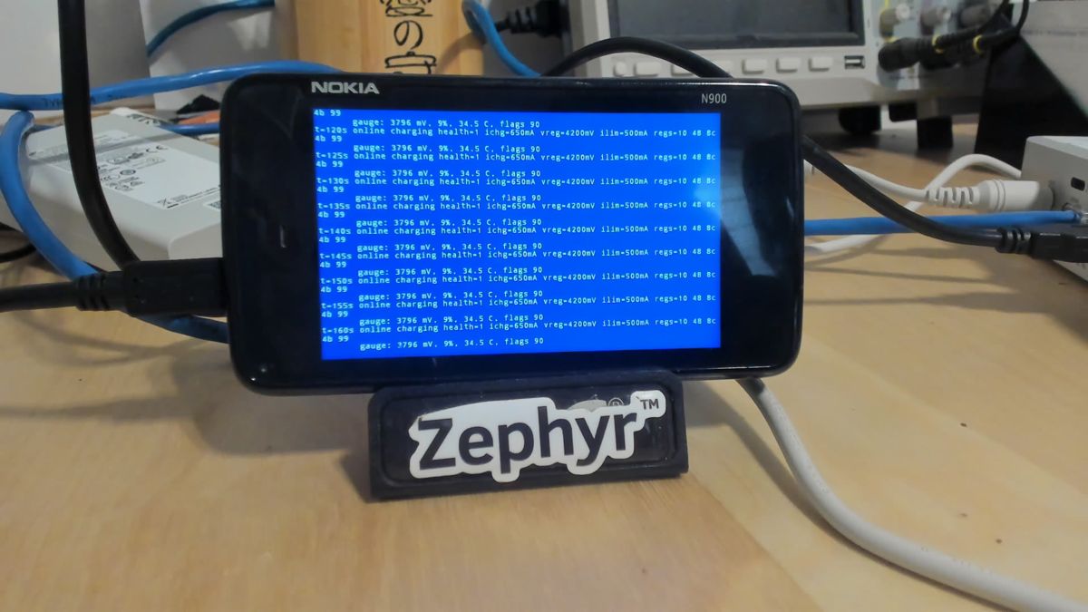 160 s later: 9%, 34.5 °C
Zephyr does not watch the battery temperature yet; the charger chip on the N900 has no thermistor input. For now the phone charges on the desk where it can be seen.
A phone that won’t turn off
Charging changed how the phone behaves on the bench. While Zephyr resets the charger’s safety timer, the bq24150A powers the phone straight from USB, so pulling the battery no longer cuts power. Until then, pulling the battery was how every test run ended.
The fix was a software reset. sys_reboot() on OMAP3 now sets RST_DPLL3 in PRM_RSTCTRL (0x48307250, bit 2), the global reset Linux uses on this SoC. After a reset the phone comes back up in NOLO, still on USB, and the waiting loader sends the next image.
Ztest already has an option for the rest: CONFIG_ZTEST_RETEST_IF_PASSED reboots the board after a passing run and leaves a failing one on the screen. Together they turn the bench into a hands-off loop. A passing suite reboots into the next image; a failing one stays put for the camera.
=== 14:33:04 reboottest: booted counts down 15 s, calls sys_reboot()
=== 14:33:21 common: booted 17 s later: back in NOLO, next image loaded
=== 14:34:30 context: booted common passed and rebooted itself
14:34:47 context passed and rebooted; nobody touched the phone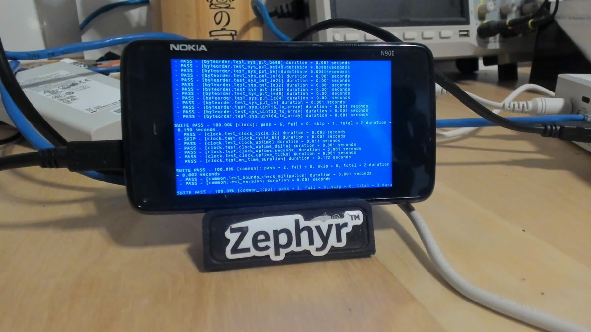 14:34:25 · kernel/common summary, seconds before it rebooted itself
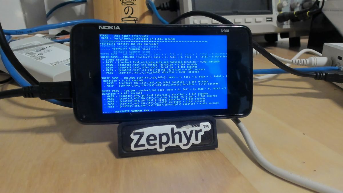 14:34:46 · kernel/context passing on the final timer
A fuel gauge and a temperature guard
Charging without watching the battery temperature was the one real gap, and the N900’s charger has no thermistor input. The bq27200 fuel gauge at I2C2 address 0x55 does measure it, so it got a driver behind Zephyr’s fuel-gauge API. The conversions follow the Linux bq27xxx_battery driver: current and capacity count 3.57 µV and 3.57 µVh across a 20 mΩ sense resistor, temperature counts in 0.25 K, and the current’s sign comes from the CHGS flag. Reading each 16-bit register in one transaction also fixed the earlier voltage reading that stayed stuck at 3796 mV.
The board now reads the battery temperature every 10 seconds and charges only between 0 and 45 °C, resuming 3 °C inside the window. If the temperature can’t be read, charging stops. To prove it, a test build lowered the limit to 30 °C while the battery sat at 34.9 °C:
n900: battery at 34.9 C, charging stopped
t=  0s not charging | 3875 mV  304 mA 34.9 C 24% tte=65535 ttf=459
t=  5s not charging | 3783 mV  -11 mA 34.6 C 24% tte=2626
t= 10s not charging | 3778 mV -243 mA 34.6 C 24% tte=123
t= 20s not charging | 3770 mV -243 mA 34.4 C 24% tte=123
The current reverses from +304 mA to −243 mA as the phone switches from USB to its own battery. The test build then rebooted itself into the normal one, which went back to charging.
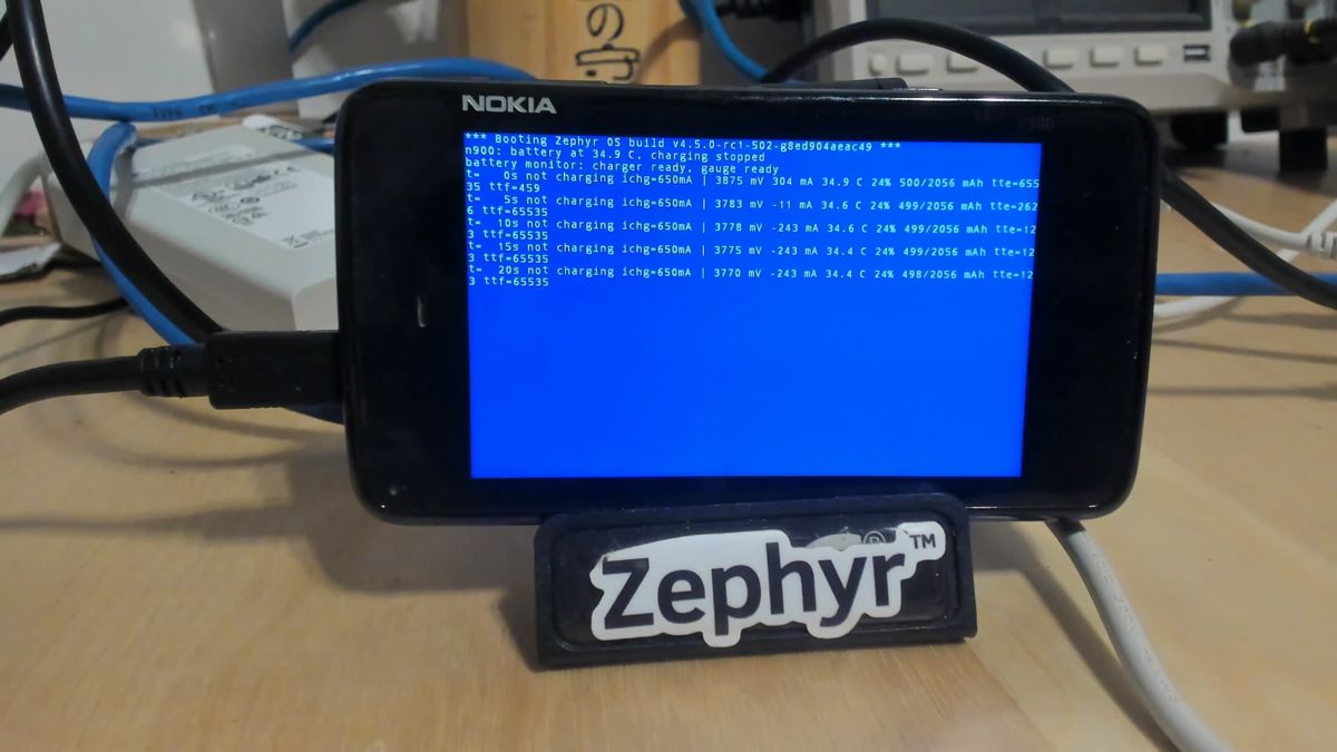 30 °C test limit: charging stopped, the phone runs from the battery
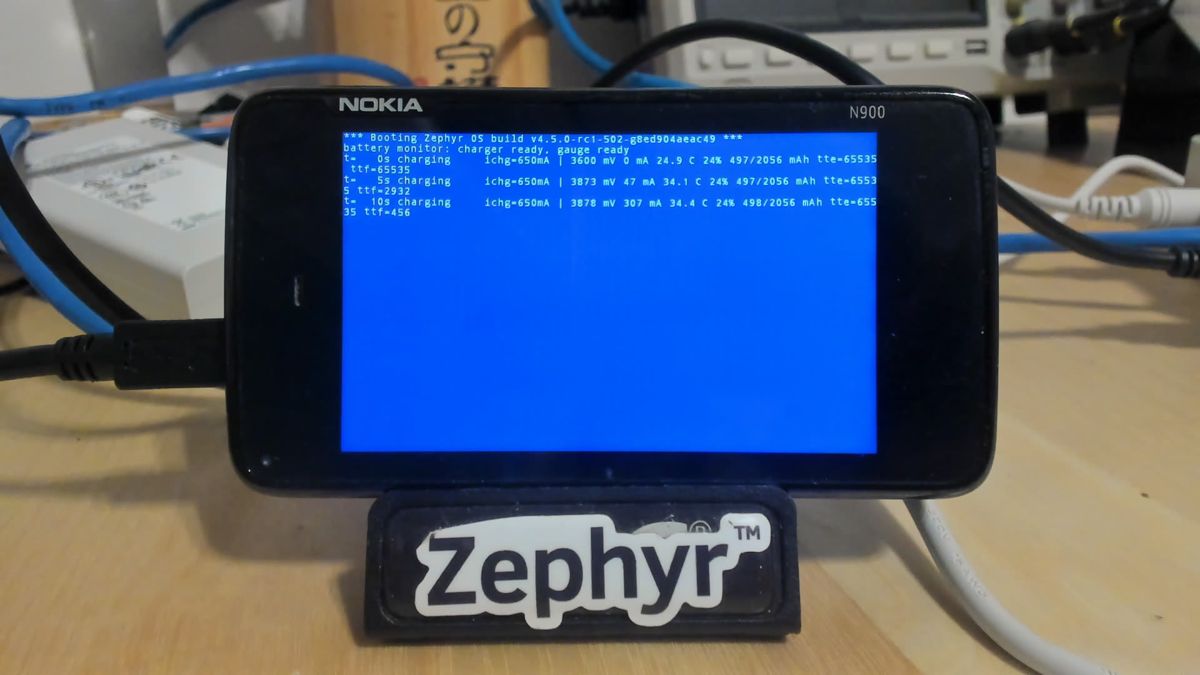 Normal limits: charging at +307 mA, 456 minutes to full
One reading needed a look: the gauge reports a full capacity of 2056 mAh for a 1320 mAh BL-5J battery. The explanation came later: it is the gauge’s uncalibrated factory value.
The keyboard
The N900’s slide-out keyboard is an 8×8 matrix that the TWL5030 power chip scans and debounces in hardware. Its keypad module sits at I2C address 0x4A on I2C1, with eight row registers that show which keys are down. The driver polls those eight bytes every 20 ms in one burst, which takes about a millisecond at 100 kHz, and reports a row and column event for each change. Zephyr’s input-keymap turns those into key codes using the N900 keymap from the Linux devicetree. The first version polled; the next one moved to the interrupt.
Two details came from the Linux twl4030_keypad driver. A row that reads 0xFF is tied to ground and stands for a ninth, virtual column, which is where F9 to F11 live. Combinations where two rows share a column with several keys down can’t be decoded, so those states are skipped. The LCD console also learned backspace.
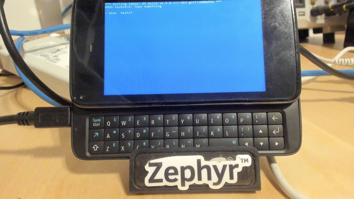 First keystrokes: “anas Nashif”, with Shift giving the capital N
From polling to interrupts
The TWL5030 raises key changes on its INT1 pin, wired to the OMAP3’s sys_nirq input, INTC line 7. That pin is shared by every module in the chip: GPIO, keypad, charger interface, ADC, USB and power. Before enabling it, a diagnostic app dumped every module’s mask and status registers:
--- pass 1: sys_nirq raw idle
PIH_ISR_P1     49:81 = 00
GPIO IMR1A     49:b4 = ff ff 03
KEYP IMR1      4a:e4 = 0f
MADC IMR1      4a:62 = 0f
BCI IMR1A/B    4a:bb = ff
PWR IMR1       4b:2f = 00
USB EN_RISE    48:0d = 1f
USB EN_FALL    48:10 = 1f
Nothing was pending, but NOLO leaves the power-button and USB interrupts enabled. A USB plug or a power-button press would hold the line asserted with no driver to clear it. The board now masks both at boot. The keypad driver unmasks only its key-change interrupt, masks the line in the ISR, and lets a work item read the clear-on-read status and the matrix over I2C before re-enabling it. If the line ever fires ten times without keypad status, the driver leaves it masked and goes back to polling.
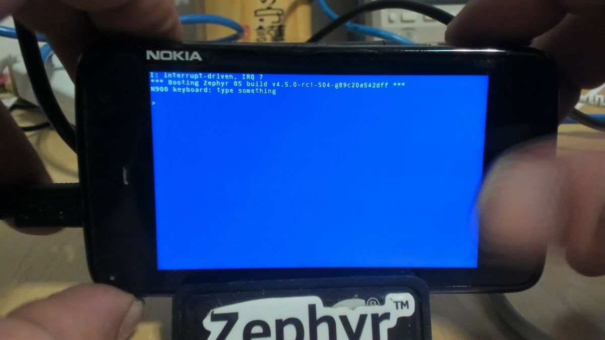 The keypad driver reports interrupt mode at boot
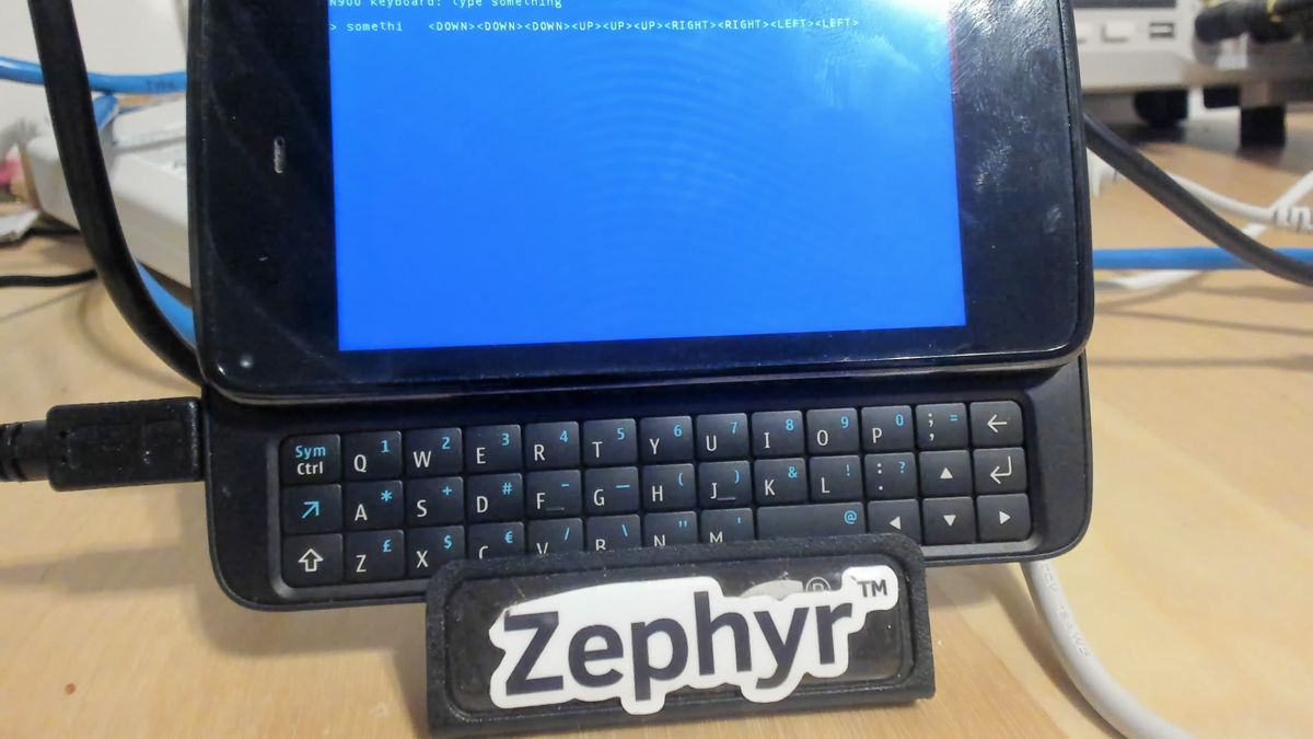 Typing, backspace and all four arrows on the interrupt
Power button and USB plug
The power button and USB plug detection come from the same TWL5030 interrupt line as the keyboard, so the keypad driver could no longer own it. A new TWL4030 MFD driver took over. It masks every module of the chip at init, owns the line, and on each interrupt reads the primary status register to see which modules fired. For each of those it reads the module’s clear-on-read status and calls the callbacks registered for it. The keypad became a child of that driver, and two power-module interrupts got users:
- Power button:
PWRON, bit 0 of the power module, on both edges. A new input driver reads the button state from the chip’s hardware conditions register (0x4B:0x45, bit 0) and reportsINPUT_KEY_POWER. - USB plug:
USB_PRES, bit 2 of the same module. Zephyr’s input subsystem has no switch events, so applications register a callback with the MFD driver and read VBUS from bit 7 of the same register.
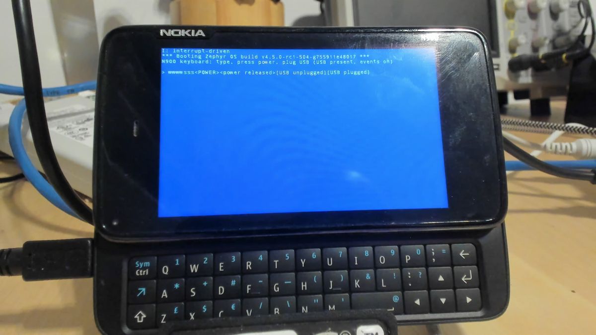 Keys, a power button press and release, and a USB unplug and replug, all on one interrupt line
The touchscreen
The N900’s resistive touchscreen is driven by a TI TSC2005 on the first McSPI controller, chip select 0. It raises a data-available line on GPIO 100 when it has samples, and its reset is on GPIO 104. That took four new pieces: an OMAP3 GPIO driver, an OMAP3 pinctrl driver, OMAP2/3 support in the existing McSPI driver, and a TSC2005 input driver.
Zephyr already had a McSPI driver for TI’s newer K3 parts, and the OMAP3 block is the same IP with every register 0x100 lower and no HWINFO register. A second compatible, ti,omap2-mcspi (the name Linux uses), carries the register offset and a fixed 64-byte FIFO. Before any of it ran, a pad diagnostic confirmed that NOLO already muxes McSPI1 and both touchscreen GPIOs, and that it leaves the TSC2005 held in reset.
Bug 1: a page table the MMU can’t see
The first touch build died during boot with a data abort in McSPI init, a translation fault on its own register window.
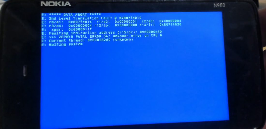 A translation fault on a mapping the kernel had just created
Every earlier driver used the SoC’s fixed identity map; pinctrl and McSPI were the first to map registers at run time with DEVICE_MMIO_MAP. On the Cortex-A8 the hardware table walk doesn’t look in the L1 data cache, and Zephyr’s ARMv7 MMU code never cleaned the entries it wrote, so the walker read the old, empty descriptor from memory. The fix cleans the page tables to the point of coherency before every TLB invalidation. It’s an arch fix that any core without coherent table walks needs.
Bug 2: talking to the panel by accident
The next build booted, and the screen went black one second after the first touch. The LCD panel’s controller sits on the same McSPI1 bus, on chip select 2. The McSPI soft reset leaves every chip select active-high, and the driver only fixed the polarity of the channel it was using, so the panel’s active-low select was asserted during every touchscreen transfer. The TSC2005’s read command is 0x01, which the panel takes as a software reset. The driver now sets every channel to active-low at init.
Bug 3: one register per transfer
With the screen staying on, touches produced nothing. A debug build printed the raw samples and the GPIO registers:
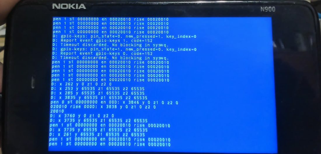 The lock switch working through gpio-keys (code 152), and samples where only X is valid
The pen interrupt fired and X tracked the stylus, but Y, Z1 and Z2 read as 0 or 65535. The TSC2005 doesn’t auto-increment within one transfer; Linux reads it with use_single_read. One register per transfer fixed it. The same frame showed the new GPIO driver at work: the lock switch reported press and release through gpio-keys.
Calibration
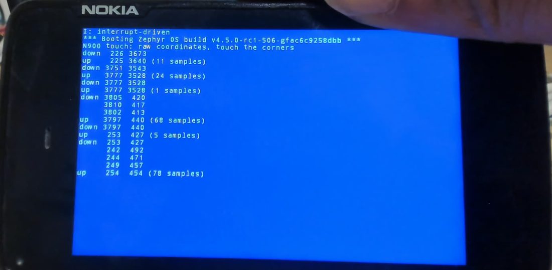 Raw samples at the four corners: X runs left to right, Y bottom to top
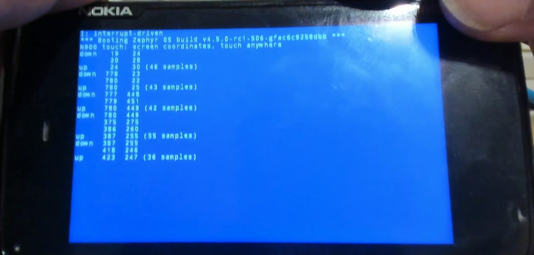 Calibrated: (24,30), (780,25), (780,449) and the centre at (387,255)
The raw corners matched the calibration Maemo used on this panel, so the board devicetree takes those edges (X 204–3897, Y 178–3763 with Y inverted). The driver scales them to the touchscreen size, and the common touchscreen code scales to the 800×480 display, so applications get screen pixels.
With a zephyr,lvgl-pointer-input node in the board devicetree, LVGL takes the touchscreen as its pointer with no application changes. In the stock LVGL sample, tapping “Hello world!” resets the counter.
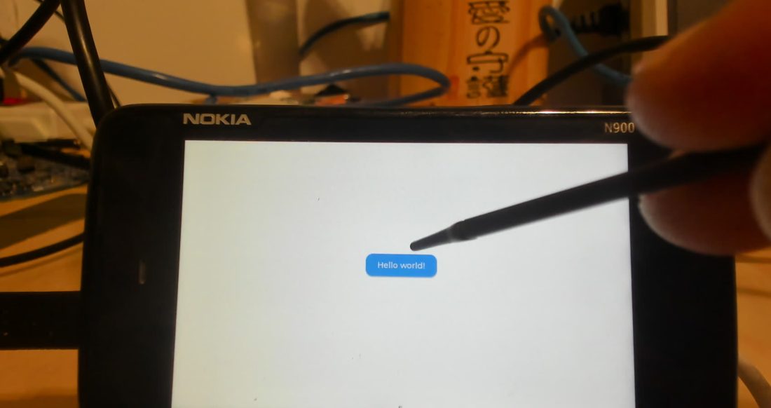 The unmodified LVGL sample, driven with the stylus
A reboot button
Every new image still needed a power cycle: once Zephyr runs, the host can’t reach the phone, because only NOLO speaks USB and the serial pads aren’t wired. The board now restarts the phone when the power button is held for two seconds; shorter presses still reach applications as INPUT_KEY_POWER. It uses the TWL interrupt directly, so even hello_world and the kernel tests get it.
The first try fired the reset but left the phone in the OMAP boot ROM’s USB mode (0421:0106), stuck there. A USB log of the next attempt showed the ROM handing over to NOLO within a second when nothing touched it. The flasher that had been waiting for the phone had grabbed the ROM’s USB device, and the ROM stalled. NOLO itself then gave up after about a second and booted Maemo, because nothing was ready to send an image in time.
A small host loop fixed both: it polls sysfs every 50 ms for NOLO’s 0421:0105 and only then starts 0xFFFF, so the flasher never touches the boot ROM and still catches NOLO’s one-second window. Holding the power button now reloads the next image with nothing else to do.
Switches and the camera key
Besides the keyboard, the N900 has a two-stage camera key and four sensors that are really switches: the keyboard slide, a proximity sensor next to the earpiece, the camera lens cover and the back cover. All sit on OMAP3 GPIOs that NOLO leaves muxed, so the new GPIO driver and gpio-keys cover them; the GPIO numbers and polarities come from the Linux devicetree.
Zephyr’s input subsystem had no way to say “switch”. Linux reports these as EV_SW events with a state rather than key presses, and a switch’s state matters before it ever changes. Three small input changes, each its own commit:
INPUT_EV_SWand the Linux switch codes (INPUT_SW_KEYPAD_SLIDE,INPUT_SW_FRONT_PROXIMITY, …), withinput_report_sw().INPUT_KEY_CAMERAandINPUT_KEY_CAMERA_FOCUS.- A
zephyr,input-typeproperty ingpio-keys; a switch reports its state once at init. Thegpio_keystest gained a switch case and passes onnative_sim.
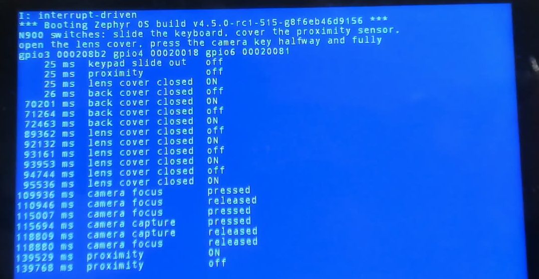 Initial states at 25 ms, then the back cover, lens cover, the camera key’s two stages and the proximity sensor
The light sensor
The ambient light sensor next to the earpiece is a TAOS TSL2563 on I2C2. A raw diagnostic read its ID register as 0x70, part number 7. Zephyr’s TSL2561 driver refused anything but part number 5, but the TSL2563 is the same chip family with the same registers and the same T-package lux equation, so the driver now accepts both.
The first raw readings looked dead: 3 counts on one channel and 0 on the other, in a lit room. The sensor sits behind the dark front glass, which Linux’s N900 settings treat as passing about 1/16 of the light, and the diagnostic used the power-on gain of 1x. At gain 16x with 402 ms integration it responds: about 1 lux in room light, and up to 22 lux with a flashlight on it. The driver reported whole lux and nothing corrected for the glass; both were fixed later.
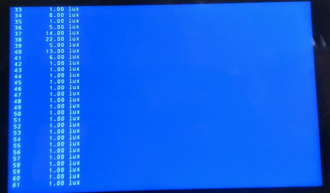 Lux readings every half second as a flashlight passes over the sensor
The accelerometer
The N900’s accelerometer is an ST LIS302DL on I2C3 at 400 kHz, an early part with 8-bit samples that none of Zephyr’s LIS2/LIS3 drivers handles. A new polled driver checks WHO_AM_I, switches on the three axes, and converts samples with the datasheet’s typical 18 mg per count. It worked on the first boot: NOLO leaves the sensor’s regulator on and the I2C3 pins muxed.
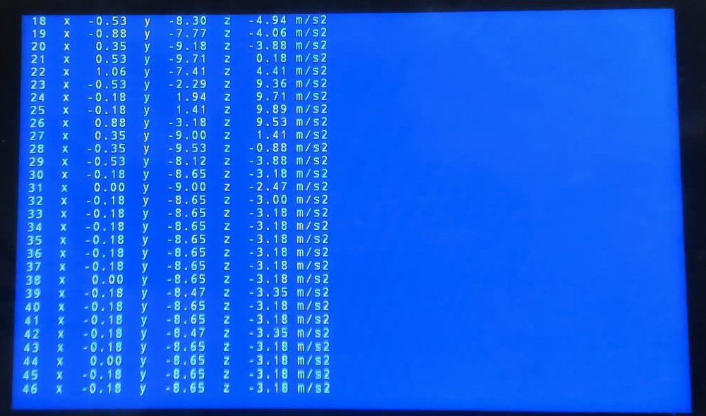 Gravity moving between the axes as the phone tilts, then steady in its stand at about 9.2 m/s²
Lying flat it read 9.7 m/s² on Z; in the stand the total is about 9.2, within the sensor’s sensitivity tolerance. The driver joined the build_all sensor test, whose nine configurations build.
LEDs, backlight and a stuck bus
The keyboard backlight and the RGB status LED hang off a TI LP5523, a 9-channel LED driver on I2C2. Zephyr has drivers for its successor, the LP5569, but not for it, and the N900’s LEDs are rated for less than the chip’s 17.5 mA power-on current, so a new driver sets 5 mA from the devicetree as Linux does.
The screen backlight belongs to the panel itself: the Sony ACX565AKM takes DCS commands on McSPI1 chip select 2, the same bus as the touchscreen, as 9-bit SPI words whose first bit tells data from commands. Zephyr’s MIPI DBI layer can do 3-wire SPI but raises the chip select between words, so a small panel driver sends each command in one transfer, and the OMAP3 display driver forwards display_set_brightness() to it through a display-controller phandle, the pattern the STM32 LTDC driver uses.
The bus that stayed busy
The first LED build failed with a timeout, and from then on every device on I2C2 (charger, gauge, light sensor) answered -EBUSY, even across reboots. A diagnostic that read SCL and SDA through the I2C controller’s test register showed both lines high and the bus otherwise healthy, until the LP5523’s enable line rose or it was told to reset: the chip glitches the lines while it powers up, and the OMAP3 controller takes that as a start condition and waits for a stop that never comes.
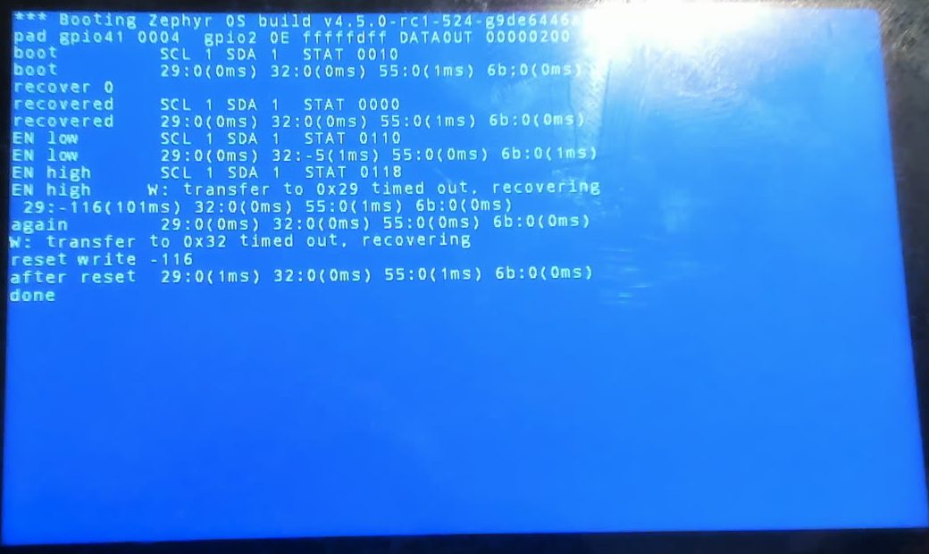 One timeout after the LP5523 powers up, then recovery: every device answers again
The I2C driver now recovers the way Linux does: on a busy bus or a timeout it clocks SCL in the controller’s test mode until any device lets go of SDA, generates a stop condition and resets the controller. It also gained a deadline check it was missing in its polling loop, which had turned the same glitch into a hang. The LP5523 driver skips the reset register and sets the registers it relies on instead.
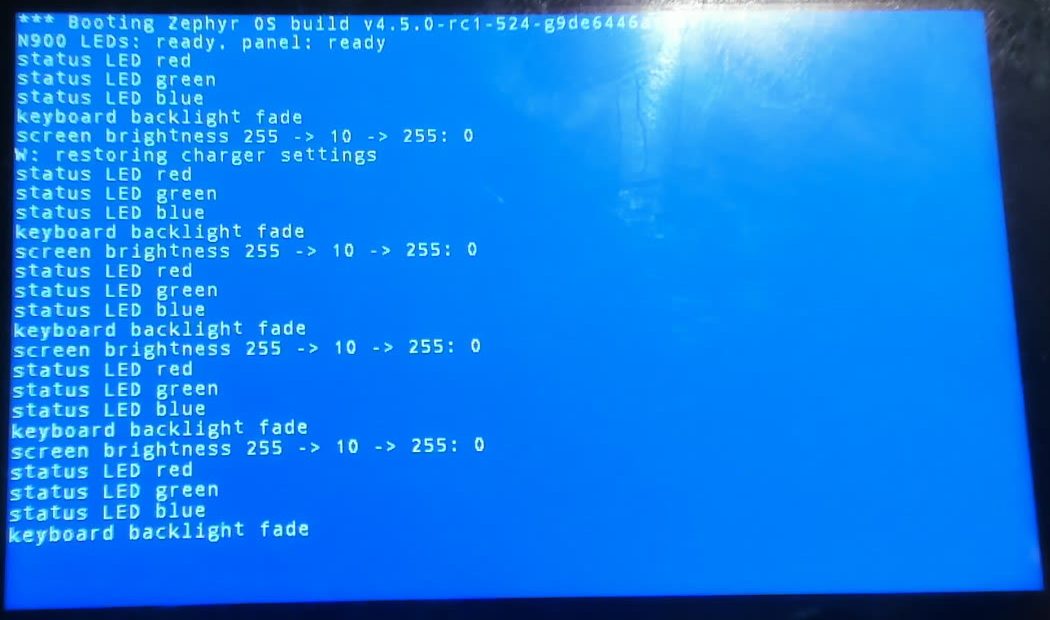 Status LED colors, keyboard backlight fades and screen brightness ramps, with a quiet I2C bus
Tap to interrupt
The LIS302DL has two interrupt lines, on GPIO 181 and 180, and can route data ready, free-fall and click detection to either. The driver now offers SENSOR_TRIG_DATA_READY on INT1 and SENSOR_TRIG_TAP on INT2, using the chip’s single-click detector on all three axes with a devicetree threshold.
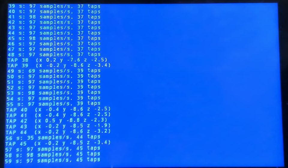 Data ready at 97–98 samples per second and taps detected while the phone sits in its stand
The first run showed a subtlety: printing each tap to the slow LCD console delayed the data-ready work, the rate dipped to 35 samples per second, and if a new sample lands before the previous one is read, the data-ready line never falls and no new edge arrives. The work now runs again while the line is still active.
The phone
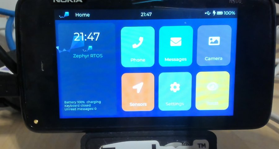
With every peripheral working, the last step was to make the N900 feel like a phone again. The demo is one LVGL application, about 1,400 lines, that runs full-screen at 800×480 with the touchscreen as pointer and the slide-out keyboard as text input. Nothing in it is simulated except the parts a Zephyr port cannot reach yet: the cellular modem and the camera sensor.
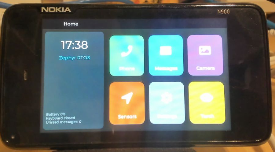 Home: clock, battery, keyboard state and six apps
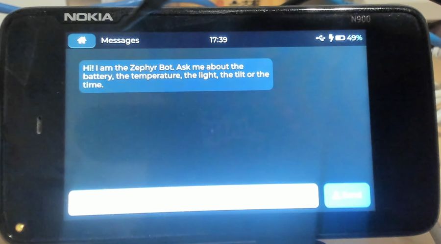 Messages, with USB, charging and battery in the status bar
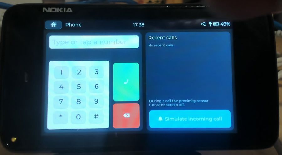 Phone: dialer, recent calls and a simulated incoming call
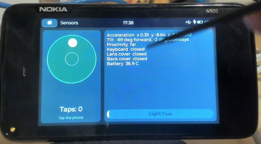 Sensors: a spirit level from the accelerometer, taps, light and switches
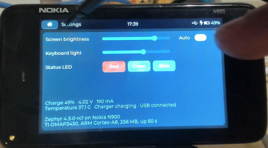 Settings: panel brightness, auto-brightness, keyboard light, LED test, battery
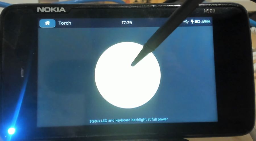 Torch: the status LED and keyboard backlight at full power
What each piece of the port does in the demo:
- Touchscreen and keyboard: LVGL pointer input; key events go through a queue into the LVGL thread, with Shift and the Fn layer for digits.
- Phone: dial on the keypad or the keyboard; the call connects after a few seconds and the proximity sensor blanks the screen next to the ear. A simulated incoming call rings from any app with the status LED blinking blue.
- Messages: a chat with a bot that answers from the hardware: ask it for the battery, the temperature, the light, the tilt or the time. Replies arriving elsewhere raise a notification and pulse the LED green.
- Camera: opening the lens cover launches it from anywhere; half-pressing the camera key locks focus, a full press flashes the screen and every LED.
- System: the lock switch locks and blanks the screen, a short power press toggles it and a long one reboots, a tap on the phone wakes it, sliding the keyboard out lights the keyboard backlight, and the status LED shows charging, full, calls and unread messages.
- Sensors in the background: two threads read the accelerometer at 20 Hz and the light sensor, gauge and charger more slowly, so the 402 ms light integration never stalls the UI; auto-brightness maps lux to panel brightness.
Knocking on the camera
The main camera is a Toshiba ET8EK8 5-megapixel sensor on I2C3, streaming over a CCP2 serial link into the OMAP3 image signal processor, with an AD5820 lens motor driver beside it and an ADP1653 flash. Getting pictures needs an ISP driver and the sensor’s register tables, which exist only in GPL Linux code; so the first steps were the parts that need neither.
The flash works: a new ADP1653 LED driver gives a 50 mA torch and a hardware-timed 320 mA flash, and returns to torch mode only after the chip’s timer has ended the flash, since disabling the timer earlier would leave the flash current on.
The sensor does not answer yet. Five diagnostic rounds powered the module one step at a time:
- VAUX4 at 2.8 V: the lens driver at
0x0cstarts answering once GPIO 102, the module’s shutdown line, goes high, so power and shutdown work. - The camera power domain was on, but its clock domain was left off by NOLO; forced awake, the ISP becomes accessible and its timing block divides the 172.8 MHz camera clock by 18 to 9.6 MHz, as Linux does.
- VAUX2 (the CSI supply) and the PLL’s camera output were already on.
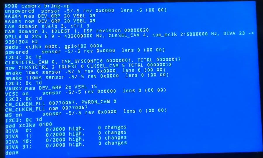 Every rail and clock matches Linux, the lens answers at
 0x0c, the sensor at 0x3e stays silent
An attempt to watch the clock pin through its GPIO input read it low at every divider setting, including the one that holds it high, so the method cannot see the pin in camera mode. Whether the 9.6 MHz clock reaches the sensor is the open question.
First light
The missing piece turned out to be in the I2C driver. Its transfer loop treated the transmit-ready flag as “data ready” in a read too, and that flag stays set while the transmit FIFO has room; a read after a register write took the data register before the byte arrived, and the real byte leaked into the next transfer. Fixed, the sensor identifies itself as revision 2 of the ET8EK8.
The rest was explored live over the USB shell with devmem, without a reboot per experiment: the CCP2 receiver configured for data/strobe signalling, the sensor’s power-on settings written from a host script that reads them out of the Linux driver at run time (they are GPL, so they stay out of the tree), and streaming started. The receiver reports frame start, frame end and line events with good CRCs. Its memory write port, which Linux never uses, takes a format code the Linux headers don’t list; a sweep found code 0x15 writes 10-bit samples into 16-bit words. Every 64th line pair, pulled over the shell and demosaiced on the host, shows the room behind the phone.
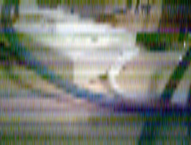 First frame from the ET8EK8, every 64th line pair, default exposure
A live viewfinder
The next step was a Zephyr application doing the whole sequence itself. It uses the sensor’s 648×492 mode at 30 frames per second instead of the full 5 megapixels; the register lists are generated into the build directory from the local Linux tree at build time, so no GPL data sits in a source file. Each frame, the receiver writes 10-bit samples into a buffer, the CPU invalidates the cache over it, converts each 2×2 Bayer cell to one colour with black level, gray-world white balance and gamma, and draws a 640×480 preview. A simple auto-exposure raises the exposure time first and then the analog gain. The preview runs at 15 frames per second without a single CRC error; indoors the exposure sits at its limit with 8× gain.
 Live viewfinder: the bench behind the phone at 15 frames per second
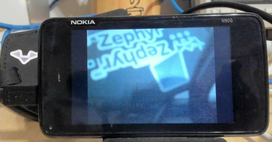 A Zephyr logo held in front of the lens; the sensor is mounted upside down, so the image needs a 180° turn
A camera in the phone
The phone demo’s Camera app used to pretend. It now runs the camera from its own thread: a triple-buffered live preview turned the right way up, contrast autofocus that sweeps the AD5820 lens actuator coarse and then fine when the camera key is half-pressed or the preview tapped, and 640×480 photos with full-resolution colour interpolation, kept in RAM and shown full screen from a thumbnail. With the flash on, the ADP1653 fires its 500 ms pulse and the exposure settles on the lit scene before the shot. The red indicator next to the lens is lit while the camera runs, and opening the lens cover opens the app. The Torch app now drives the flash LED in its torch mode instead of the status LED.
The first image with the camera in it never got past the NOLO logo: the photo and preview buffers made it 15.6 MB, twice the 8 MB of kernel virtual address space, and the build gave no warning. A larger CONFIG_KERNEL_VM_SIZE fixed it.
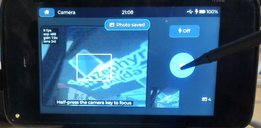 The Camera app: live preview with exposure readout, focus box, flash toggle and the newest photo
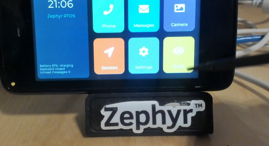 The Torch app, now lighting the real flash LED
USB: a console without a camera
Until now every log line on this page was read through a webcam. The N900’s USB port is a Mentor Graphics MUSB high-speed OTG controller with an NXP ISP1707 ULPI PHY, and Zephyr had no driver for it, so a new device controller driver for the current USB stack came next: endpoint FIFOs filled by the CPU, a fixed 512-byte FIFO slot per endpoint, and the work done in a driver thread under the UDC lock.
NOLO, which uses the same controller for flashing, leaves it configured: ULPI mode selected, PHY powered on GPIO 67, the device side of the core with VBUS valid. The first build connected at high speed and then failed every request, and the host’s kernel log and the driver’s debug output on the screen took it apart one bug at a time:
- STALL on the first request: the idle bus raises a suspend before the host’s reset, and nothing cleared it, so the stack refused every transfer on a “suspended” device.
- Still STALL: the Kconfig did not declare high-speed support, so the stack built only full-speed descriptors while the controller connected at high speed.
- Timeout: the stack queues the status-stage buffer together with the data stage; the driver started the status stage first and never sent the data.
- Protocol error: EP0 has a single FIFO, so the SETUP packet has to be released before the reply is loaded, which is what Linux does.
Then the host printed ttyACM0: USB ACM device. The CDC ACM sample echoed 256 KB of random data intact at 2.6 MB/s round trip, and the shell sample with the cdc-acm-console snippet answered on the NUC:
uart:~$ kernel version
Zephyr version 4.5.0-rc1
uart:~$ device list
devices:
- usb@480ab000 (READY)
  DT node labels: usb_otg zephyr_udc0
- i2c@48060000 (READY)
- pmic@48 (READY)
- charger@6b (READY)
- fuel-gauge@55 (READY)
  ...
uart:~$ demo board
n900
A small hwinfo driver then gave the device an identity: the OMAP3’s 128-bit factory die ID, which the USB stack turns into the serial number the host sees, 106A00040000000004036C790F018002. The driver also decodes the reset status of the power and reset manager, but after a reboot through NOLO it reads empty; presumably the bootloader consumes it.
Turning the screen
The OMAP3 display controller can only rotate by 90° through its VRFB rotation engine, so rotation happens in software. LVGL 9 leaves that to the flush callback, and Zephyr’s LVGL glue did not do it, so a new CONFIG_LV_Z_SW_ROTATION option rotates each rendered area into a second buffer with lv_draw_rotate() and moves it to display coordinates, for any 16, 24 or 32-bit Zephyr display. LVGL already maps touch points for a rotated display.
The phone demo reads gravity from the accelerometer, waits half a second for a new orientation to settle and rebuilds its layouts for the new resolution: in portrait the home screen, dialer and sensor panels stack vertically. Sliding the keyboard out forces landscape, as on the real N900.
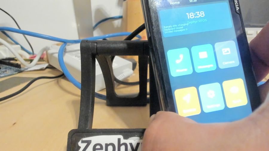 The home screen follows the phone into portrait
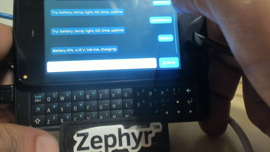 Back in landscape with the keyboard out: the bot reports the battery
Three loose ends
The light sensor. The TSL2561 driver rounded its fixed-point result to whole lux, so a dim room read 1 and the next step was 2. It now converts to micro-lux. A new glass-attenuation property, written like the TSL2540’s, scales the reading for whatever covers the sensor, and the N900 sets it to 16 as Linux does for the front glass. Raw counts of 33 and 6 that used to read 1 lux now read 12.92 lux.
The gauge capacity. Reading the BQ27200’s registers settled the 2056 mAh question. The full capacity register holds 11520 counts, exactly the initial value in the gauge’s EEPROM (0x2d × 256). The capacity-inaccurate flag is set and both cycle counters are 0: this gauge has never completed a learning cycle, which takes a full charge followed by a discharge to the empty threshold. 11520 counts at 3.57 µVh across 20 mΩ is 2056 mAh, so the driver’s arithmetic is right and the number is the factory placeholder, not a measurement.
The console. Every new console line used to copy the whole framebuffer, 750 KB of uncached memory, up by one text row. The reserved region holds two copies of the text area, so the console now draws each character into both copies and scrolls by moving the display layer’s base address down one row. When the window reaches the second copy it wraps back to the first, which has the same contents. A test printing 200 lines took 27.7 s before and 211 ms after: 138.6 ms per line down to 1.06 ms.
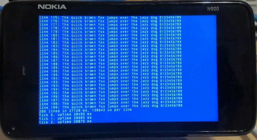 Before: 138642 µs per line
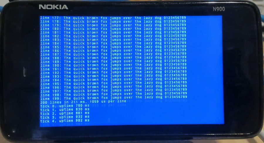 After: 1059 µs per line
Floating point
Until now the port compiled every float operation into a library call. The Cortex-A8 has a VFPv3 unit with 32 double-precision registers plus the NEON SIMD unit, and Zephyr already handles both on Cortex-A: it enables the coprocessors at reset and saves d0–d31 lazily on context switches. The OMAP3 SoC only had to select VFP_DP_D32 and NEON, and the compiler flag table needed a Cortex-A8 entry (-mfpu=neon). That table’s outer block was never indented, so the CMake style check rejected any new line in it; a whitespace-only commit fixes that first.
A benchmark built both ways, on the 499 MHz CPU with caches and L2 on:
| Test | Soft float | VFP | Speed-up |
|---|---|---|---|
| float multiply-add ×200k | 20.3 ms | 14.4 ms | 1.4× |
| double multiply-add ×200k | 42.8 ms | 16.4 ms | 2.6× |
| sinf ×20k | 42.2 ms | 20.4 ms | 2.1× |
| sqrt ×20k | 35.0 ms | 3.3 ms | 10.6× |
| float vector 200×1024 | 28.9 ms | 25.8 ms | 1.1× |
| same, NEON intrinsics | – | 4.5 ms | 6.4× |
The scalar numbers are modest because the A8’s VFP is the non-pipelined “VFPLite”: every instruction finishes before the next starts. NEON is the fast path for single precision, but GCC only uses it for plain float code with -ffast-math, since NEON flushes denormals. Written with intrinsics, the vector loop runs 5.7× faster than on the VFP. The stock fpu_sharing test, where threads of different priorities interleave FPU work, passes on the phone, and so does float_disable, which turns a thread’s FPU access off and back on (its interrupt case is skipped without dynamic interrupts).
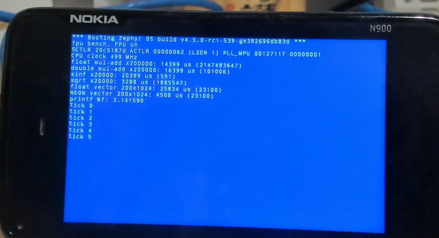 Hard float: 499 MHz, NEON vector loop in 4.5 ms
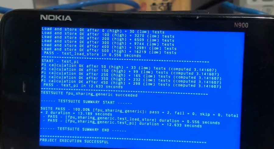 kernel.fpu_sharing.generic: load/store and pi tests pass
Sound, vibration and kites
The vibration motor hangs off the TWL5030’s audio block, which drives it with a PWM. A new haptics driver powers that block and its PLL only while the motor runs and reads the PLL’s reference frequency from the chip’s boot configuration. The phone now buzzes with the ringtone, on a bot reply and on the camera shutter.
Sound took three drivers. The loudspeakers hang off a TLV320AIC34 codec on I2C2, fed audio by the OMAP3’s McBSP2 serial port. The first attempt found the codec silent on the bus: its 2.8 V analog supply, VMMC2, is off when NOLO hands over, and Linux keeps it permanently on for that reason. With the supply on, the codec’s PLL turns the 19.2 MHz system clock into exactly 2048 × 48 kHz, and McBSP2’s buffer drained at 96,181 words a second, two channels at 48 kHz. Six beeps came out of the speakers.
The test then became Zephyr drivers: an I2S driver for the McBSP, interrupt-driven from its 1280-word buffer with start, drain and underrun handling; an audio codec driver for the TLV320AIC3x family that computes PLL settings for any master clock, with volume and mute; and a driver for the TWL5030’s 18 GPIOs, one of which enables the speaker amplifier. An arpeggio played through the standard APIs, each pass 6 dB quieter than the last.
The phone demo has a sound thread that synthesizes its sounds and keeps the amplifier off when quiet: DTMF tones on the dial pad, ringback and a ringtone, a message chime, a shutter sound, a startup chime, key clicks, and a volume slider in Settings. And it now carries the Zephyr kite: the artwork from the documentation, converted to LVGL images at build time, flies in on the boot splash, drifts across an evening sky behind the home screen, sits in the status bar and watches over the lock screen.
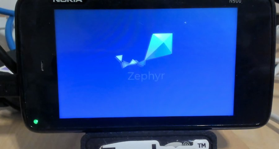 The boot splash: the kite flies in, then the name
Kites on the home screen, in the status bar and drifting behind the tiles
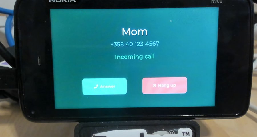 An incoming call rings and vibrates
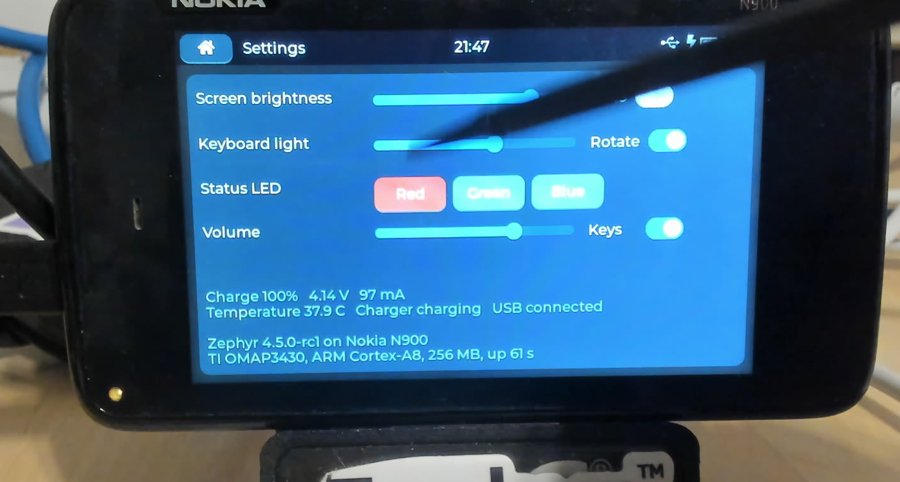 Settings with volume and key sounds
The series
The porting happend in the main zephyr tree in a branch. At the end of the day I had fifty-seven commits on topic/n900/bringup.
arch: arm: core: add Cortex-A8 support
arch: arm: aarch32: mmu: make Normal memory shareability optional
arch: arm: aarch32: mmu: clean page tables before invalidating the TLB
drivers: interrupt_controller: add TI OMAP3 interrupt controller
drivers: timer: add TI OMAP3 GPTIMER system timer
drivers: i2c: add TI OMAP3 I2C driver
soc: ti: add OMAP3 series
drivers: display: add TI OMAP3 display controller driver
scripts: west_commands: runners: add nolo runner
drivers: charger: add TI BQ24150A charger driver
drivers: fuel_gauge: add TI BQ27200 fuel gauge driver
drivers: mfd: add TI TWL4030 driver
drivers: input: add TI TWL4030 keypad driver
drivers: input: add TI TWL4030 power button driver
boards: nokia: add Nokia N900
drivers: gpio: add TI OMAP3 GPIO driver
drivers: pinctrl: add TI OMAP3 pinctrl driver
drivers: spi: omap_mcspi: default chip selects to active low
drivers: spi: omap_mcspi: support the OMAP2 and OMAP3 register layout
drivers: input: add TI TSC2005 touchscreen driver
soc: ti: omap3: add GPIO, pinctrl and McSPI controllers
boards: nokia: n900: add the lock switch and the touchscreen
boards: nokia: n900: reboot when the power button is held
input: add switch events
input: input-event-codes: add camera key codes
input: gpio_keys: support switches
tests: drivers: input: gpio_keys: test switches
boards: nokia: n900: add the camera keys and switches
drivers: sensor: tsl2561: support the TSL2563
boards: nokia: n900: add the ambient light sensor
drivers: sensor: lis302dl: add ST LIS302DL accelerometer driver
boards: nokia: n900: add the accelerometer
drivers: led: lp5523: add TI LP5523 LED driver
drivers: display: add Sony ACX565AKM panel controller driver
boards: nokia: n900: add the LEDs and the panel controller
drivers: sensor: lis302dl: add data ready and tap triggers
boards: nokia: n900: wire the accelerometer interrupts
drivers: led: adp1653: add ADI ADP1653 flash LED driver
boards: nokia: n900: add the camera flash
drivers: usb: udc: add TI OMAP3 MUSB device controller driver
soc: ti: omap3: add the USB OTG controller
boards: nokia: n900: enable USB device support
drivers: hwinfo: add TI OMAP3 hwinfo driver
modules: lvgl: add software display rotation
drivers: sensor: tsl2561: report fractional lux
drivers: sensor: tsl2561: add a glass attenuation property
boards: nokia: n900: correct the light sensor for the front glass
cmake: gcc-m-fpu: indent the CONFIG_FPU block
cmake: gcc-m-fpu: support the Cortex-A8 FPU
soc: ti: omap3: enable the VFP and NEON units
drivers: haptics: add TI TWL4030 vibrator driver
drivers: gpio: add TI TWL4030 GPIO driver
drivers: i2s: add TI OMAP3 McBSP driver
drivers: audio: add TI TLV320AIC3x codec driver
soc: ti: omap3: add the McBSP serial ports
boards: nokia: n900: add the vibrator
boards: nokia: n900: add the speaker path
Doing it right out of tree
There is no intention to make this part of Zephyr.
The idea here is to use this port as a way to show that you can do quite impressive things without being part of the zephyr tree. This is however not always easy or possible.
The port now lives in its own repository, and only 15 commits remain as changes to Zephyr itself.
The new repository (zephyr-n900, started from upstream example-application) holds the SoC, board, devicetree and bindings, all 26 new drivers, the NOLO flash runner, a driver build test, all 25 apps, the bring-up tools. Files keep the paths they had in the Zephyr tree, so upstreaming anything later is a plain copy. It’s nine commits on main.
The branch topic/n900/core is in my zephyr fork plus the 15 commits that change existing Zephyr code: Cortex-A8 support, two MMU fixes, the A8 FPU flag, the McSPI, TSL2561, input/gpio_keys and LVGL rotation changes.
What’s next
- Networking over USB: CDC-NCM and the IP stack, with a web page showing the camera and sensors.
- Camera upstream: the CCP2 receiver behind Zephyr’s video API; the sensor settings need a source other than the GPL tables.
- Bluetooth: the BCM2048 on UART2 speaks Nokia’s H4+ variant and has no Low Energy, so only Classic profiles apply.
- UART3: a serial console needs wires soldered to the test pads under the battery.
Anas NashifNot much.
[01] keep reading